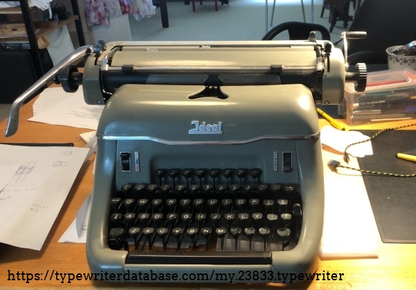
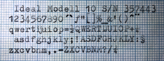
Fabulous high-class machine, in the professional Olivetti, Hermes office category.
A machine with similarity to the Urania 9 and even more so to the Urania 9a.
The machine even seems to have existed as Urania 10
Thanks to Jaap Horsting for drawings of the carriage and of the Urania 10.
Thank to Otto Koponen for his comment .Via him I found the fourth link in the list of links
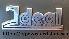
The Ideal logo in Erica font.
The traditional „Seidel & Naumann AG“ (Erica) and „Clemens Müller AG“( Urania) became "companies of the people" in 1945 and were merged into VEB Mechanik Schreibmaschinen-Werke Dresden in 1951 (new name for Urania 9a: Ideal)
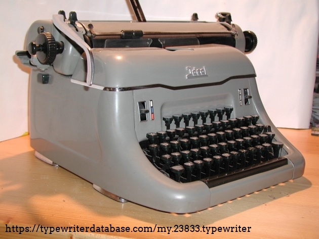
Some 20 kg of heavy metal, meaning 'no aluminium'.
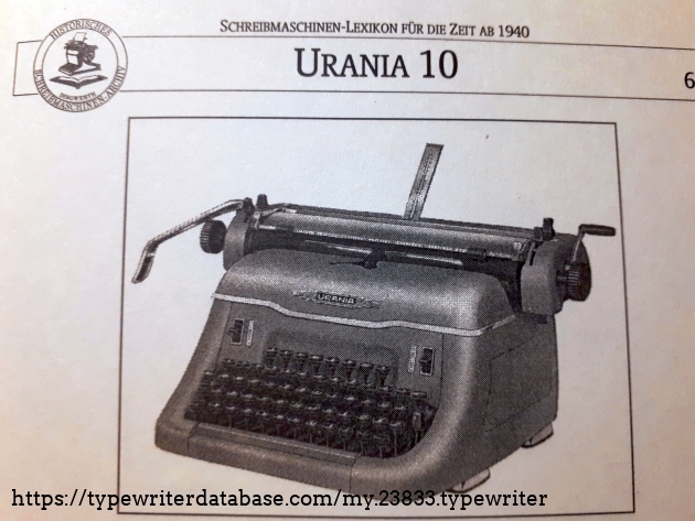
So a nUrania 10 has existed?
By Jaap Horstink
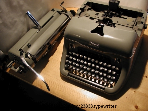
Separate carriage module, easyly removable
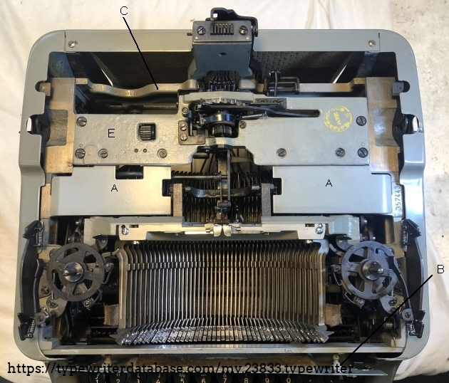
top view without carriage and top cover
At A: simple dust covers
At E: a casting with escapement and tabulator brake. Gearwheel to right of E is to set the brake force.
Below at B: the pins that clamp the 'firewall' to the base.
On top at C: the rear wall casting.
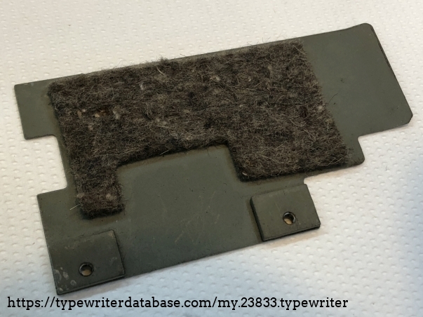
the simple dustcover is more elaborate on its botto side: reinforcement of the threadholes and sound dampening material
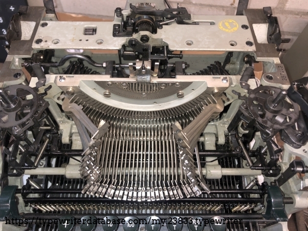
Typearm rest removed, front cross member removed, chaos photo, black colored parts everywhere
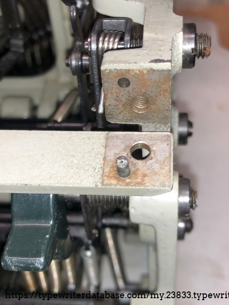
Dowel pins. For accutate positioning, front cross member and all other elements do not rely on bolts only
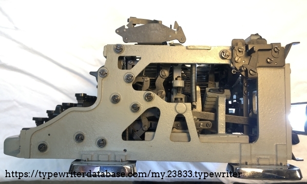
View on right side of chassis: casting milled surfaces where accuracy is required. On top: the elaborate holder of the top cover. On the right: the elaborate locking mechanism of the carriage module.
Large tension spring in the centre is balancing the weight of the segment.
Nice shoes!
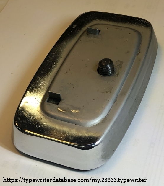
One of four big feet, all partially chromed. Bend up lips for orentation against milled surfaces of the chassis
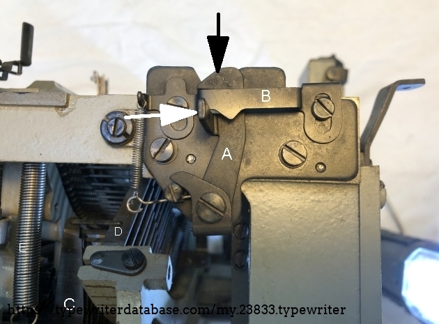
The carraige locking mechanism, right side.
To open the lock, lever A is pushed to the right (white arrow). Lever B will be lifted and return to lock lever A in the open position.
As soon as you lift the carriage out of the V-shape, lever B will go upwards at its right hand side. Lever A will return to its lock position, ready for locking the carriage when it is mounted on the machine.
Thereby, lifting the carriage is a one-person job. as is mounting it again.
When placing the carriage, the hook at the top end of lever A will give way to the right and snap back to the left and catch a robust pin on the carriage.
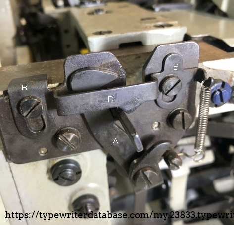
the mechanism that holds the carriage, left side. See next picture
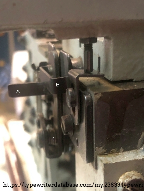
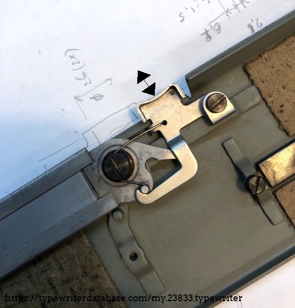
Again, the carriage locking mechanism, now with the carriage in place.
The ear at A will carry the pushbutton. At C you see the spring that forces lever A counterclockwise.
Here you see how lever b is pushed down by its ear by a pin in the top
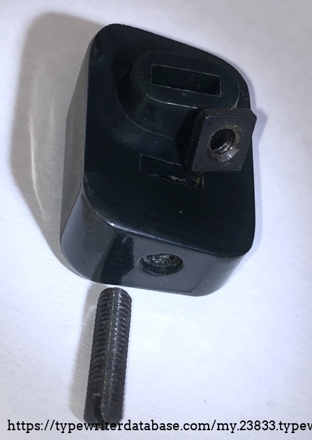
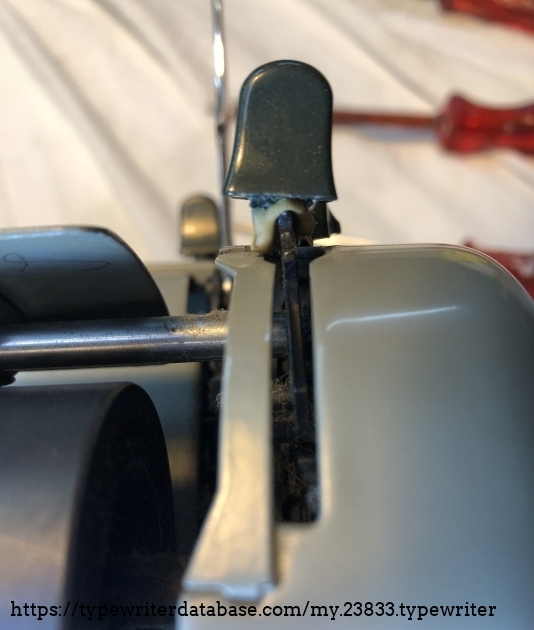
On lever A in the photo above there is this knob. No thread in the "artificial material" (Dutch for plastic, artificial as 'unnatural', or 'man made' ), In stead, high quality thread in a extra steel nut.
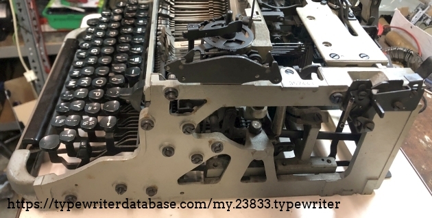
Again, view on the chassis from the right side
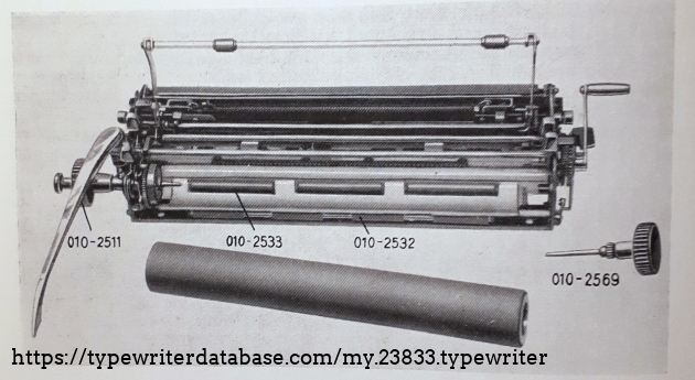
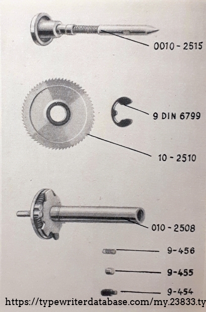
The carriage module in a drawing (thanks, Jaap Horstink). The pins of 010-2569 and 010-2511 fit in the platen with a taper and an M3 thread! The two platen knobs can be very difficult to pull, you need to screw them out against the friction in the tapers!
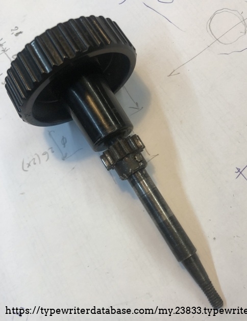
Right hand platen knob assembly with taper and thread. The paper injector engages pinion wheel
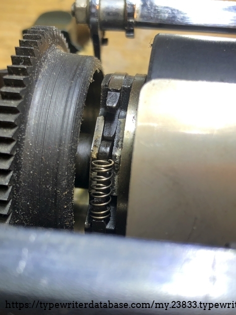
the platen freewheel clutch after I had erroneously removed the ring with number 9 DIN 6799 the drawing.
I was looking for a way to remove the platen. This was not the way. Now I only had an extra reason to remove the platen
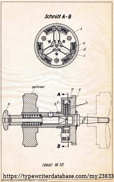
the platen freewheel clutch in a drawing. Six springs wedge six rollers d between f and sloping surfaces of two plates h. Between the plates H there are the arrows c. When button a is pushed the taper at b will force the arrows c radially ouwards and push against the springs forces. Now, the large knob and the platen can be rotated freely in relation to the ratchet.
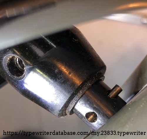
Again, how elaborate! In the actual machine the set-screw that holds a/b in place is a tiny pin in a tiny tangenially bored hole. See picture
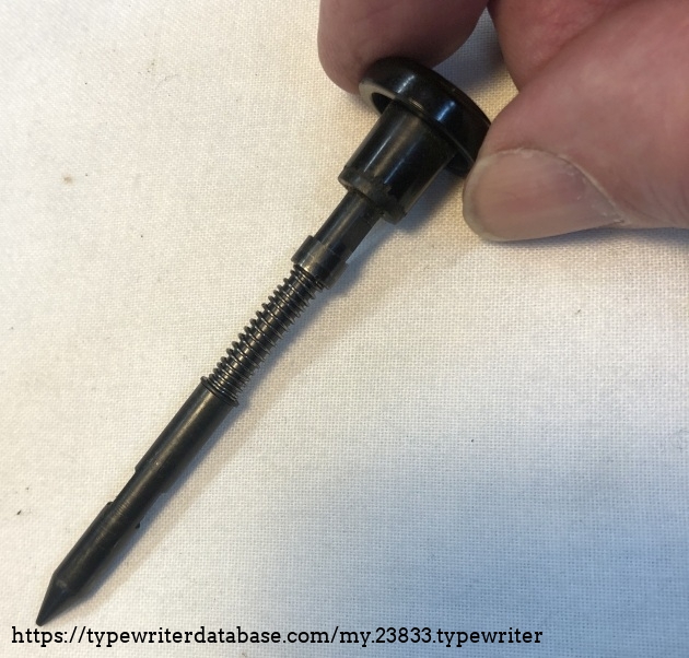
The button assembly that actuates the platen freewheel clutch
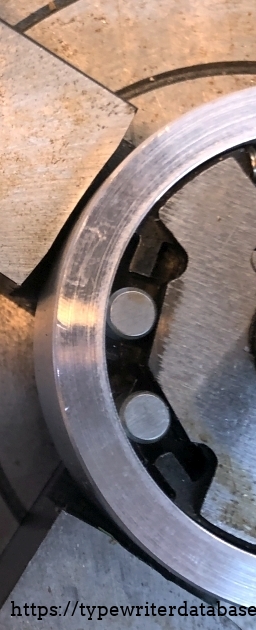
Photo of the small stubs that the springs are held on
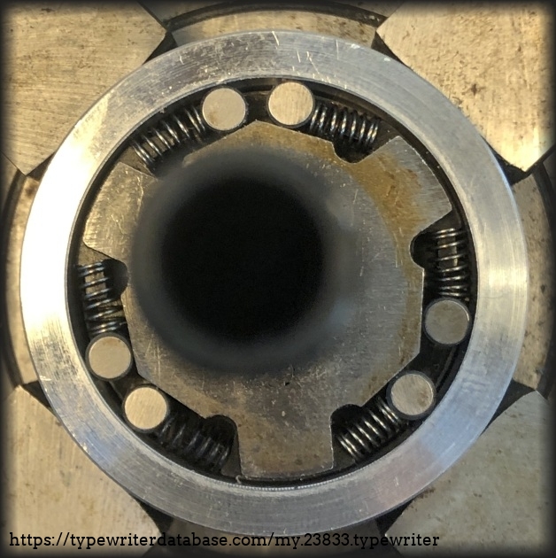
The platen freewheel clutch: six springs wedge six rollers between the outside ring and sloped surfaces. The outside ring is an assembly tool. From here the assembly can be transferred to the actual ratchet
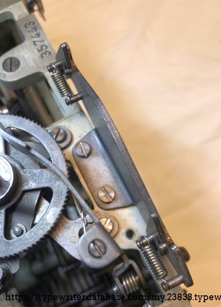
Count the parts in this assembly that merely holds the top cover. 12? So 24 in total. A lot of labour! Okay, there are only 4 design item.
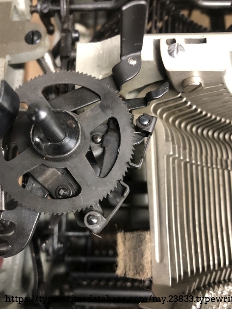
the left hand ribben transport in action: both hooks engaged
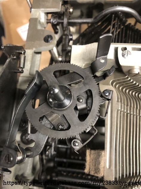
The left ribben transport out of action: both hooks permanently lifted
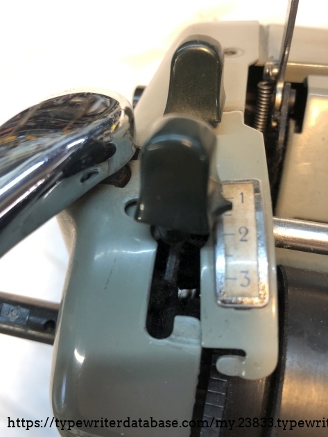
Six choices for line space. On paper behind ? In a sheet metal frame
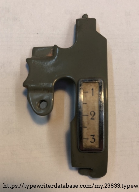
With this intricate part, the left hand cover is closed around the button for choosing line spacing. It seems that the buttons can not me pulled. Extra picture
The intracate extra part, almost in place. You don't notice the difference
earlier repair of a button
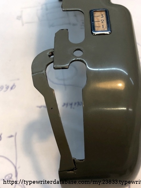
The same trick as on the left side of the carriage: an extra part to close the gap around the paper release lever.
The number on the cover indicate the stroke of the paperinjector.
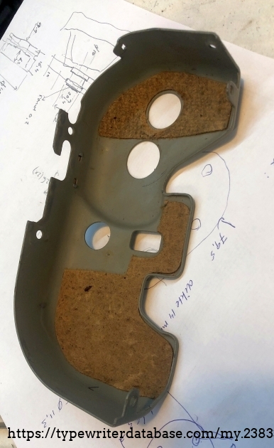
Right hand cover of the carriage. All steel, with sound proofing material
Paper support hidden. The single spring will return the know and pop up the support
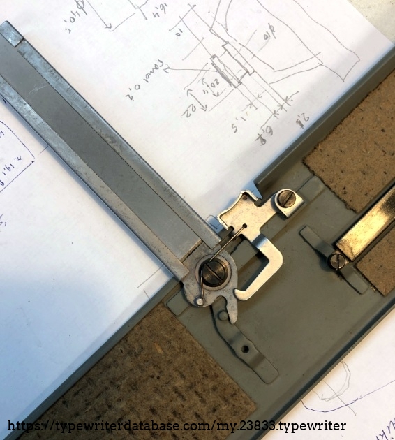
the inside of the paper support. A single spring with two functions!
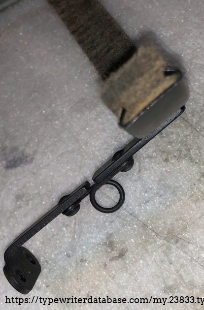
The typearms fall back into a felt. The felt clamp is supported in two springs. How elaborate can you be?
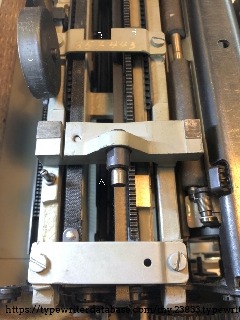
The stationary part of the carriage assembly . At A the pin that is locked in the carriage lock. At B the handwritten serial number. At C the bell.
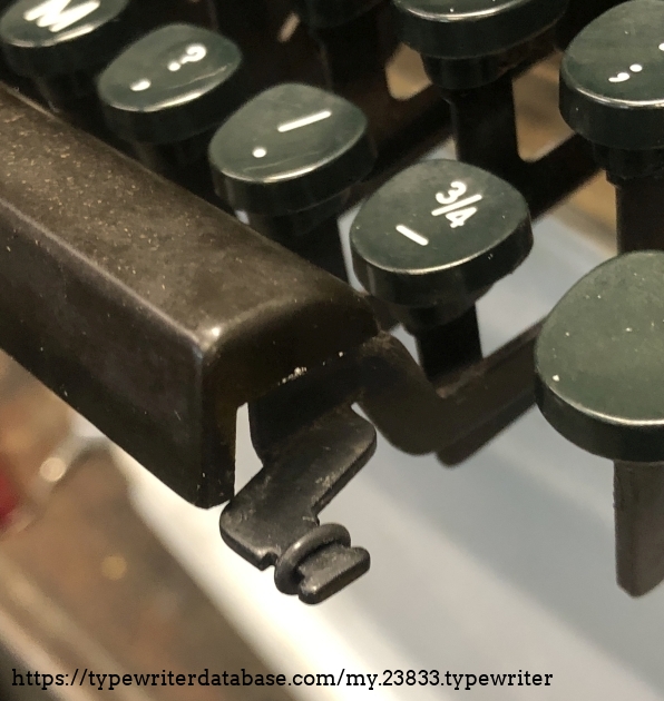
the spacebar damping rubber was gone, A O-ring will do
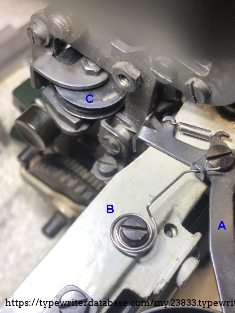
A strikes the bell, B is its actuating spring,
C is one of the two spring motors for the mechanised margin stop setting. When the green buttton is pushed and held, the spring motor pulls the (other side) margin stop towards the center, you can move the carriage back to the required position, release the button and you're set
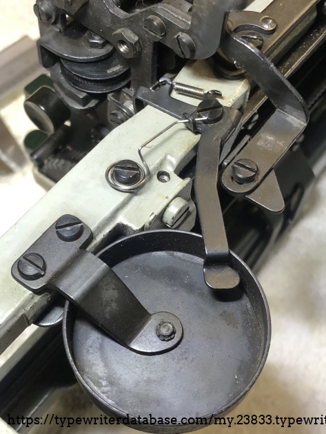
beautiful curled spring hits the bell and immediately retuns to its rest position
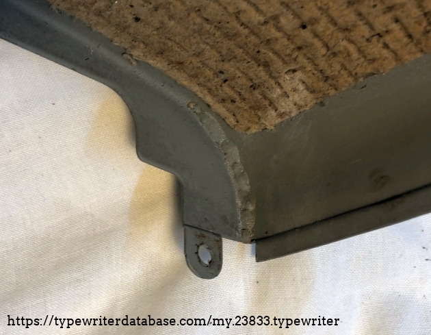
When gaps appear after bending.....
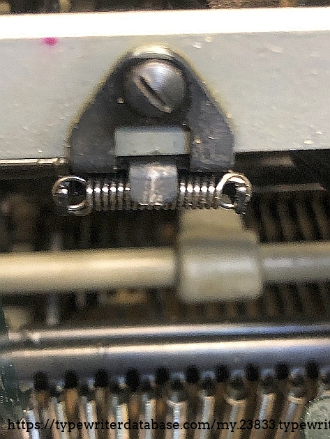
Again, why so elaborate? Two pins in the firewall (see other photo) are locked under the spring and held in position by the metal tongue
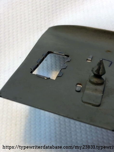
view on the backside of the firewall, where the colorselector is: thin metal frame and locating lockin pin
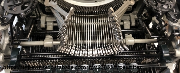
the light grey casting that stretches from left to right is the lower linkage of the four bar linkage in which the segment is the third bar, moving down for caps.

Status: Typewriter Hunter
Points: 1145
As a retired product development engineer, I am fascinated by the design of electro-mechanical products in which parts move, make noise and, preferably, radiate a little heat. Most preferred are products that are operated by keys, like typewriters, accordeons and pianos.
My genetics and statistics on lifetime expectancy suggest that it is time for me to let you know about the fantastic design, product engineering and manuacturing skills of the generation before mine. I salute mr. Munk for the opportunity that he has created for me to show it to the world. Okay, a bit bombastic.
Comments? Email me at hreinder1950@gmail.com
